VLF transmitting Experiment II
Location: Sierra Nevada Mountains
Coordinates: 37° 22' North, -119° 09' West
Elevation: 8000 ft
Click
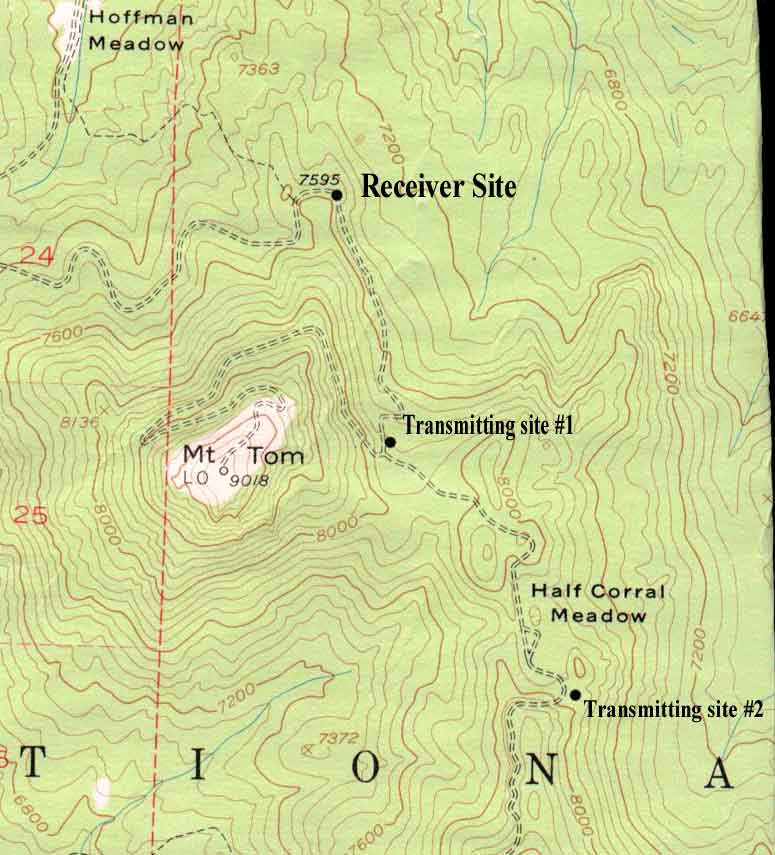
here for site map
Transmitting a VLF signal is easy. Sending it out to a great distance, on the other hand, is very
difficult. As suggested on the man-made emissions
page, listening for a particular signal is nearly impossible in the vicinity of A.C.
power lines. Listening in the midst of natural VLF radio noise (sferics, tweeks, chorus) can also be hard on the ears.
The size of the antenna and the amount of power put into the antenna determines how far the signal
will travel. There are other factors as well, like what the signal has to go through to get to the receiver,
the operating frequency, and system efficiency.
The experiment utilized B-field arrangements at both receiver and transmitting sites. The B-field method has several advantages over
E-field technique. The mountainous region is full of tall trees, which tends to deaden the reception of electrostatic
receivers. To overcome this problem, the antennas would have to be higher than the trees (the budget
of this experiment prohibited the purchasing of equipment that would propel the antenna system high above the
trees). Not so with B-field antennas. The receiving site actually used a tall tree to support the apex of the loop
antenna. Since trees have very little iron, if any at all, they do not have much influence on the magnetic component of
the signal. Another advantage over the E-field setup is the electrical grounding system requirements. The
soil of the High Sierras is very dry and non-conductive. The decomposed granite rock, tree bark and pine
needle compound does not make a good ground connection when it is dry. Transmitting a signal using the E-field
method requires an excellent earth gound connection at both receiving and sending sites.
Under construction, more to
follow...
Note from the field
The
system was B-field, using my latest B-field receiver. The antenna used at both receiving
and transmitting sites are 300 ft. triangular loops of 20 gauge wire suspended about 50 feet high at the apex. The
transmitter was very simple, A 100 watt public address amplifier (also used an LM386
chip based speaker amplifier). I designed a circuit in the field to inhibit the constant tone from the
audio frequency generator to an
on/off scheme using a 555 timer chip. The 100 watt PA was powered
with my newly installed 1800 watt AC inverter. While testing the
transmitter, I found out how fast the inverter drained the truck
battery. I ran the engine after the test. It takes about 30 amps of
current at full power output. I was by myself on this mission, I
setup a radio relay link to send the output of the B-field receiver
to my location at the transmitter sites. The radio relay is a VLF
transponder that I designed a few years ago. It uses the 2 meter
amateur radio band (145.510 Mhz). It was designed to run for 20
minutes then shut down, to conserve battery power. I modified it to
run continuously, and powered it with a fully charged car battery. I
picked a spot about a mile away from the receiver. It was a nice,
clear, flat area to setup the antenna. First, I hooked up the 100
watt amp to the antenna, turned on the audio generator to send out
the signal, I was a little surprised at the received signal strenth.
Then tuned the frequency of the generator to find out the optimum
power output. 1.5 to 2.0 Khz seemed to be the best range for
transmitting. I could hear the transmitter from 600 Hz to 5 Khz (5
Khz is the upper limit of the VLF transponder radio link). The low
power transmitter was my radio shack mini amplifier speaker. It has
a rated output of 500 milliwatts when powered with a nine volt
battery, I almost couldn't beleive my ears when I heard the tiny
(one-half of a watt) signal in between the loud background static.No
problem hearing the signal here, it was very loud. The alternator in
my truck whined a bit when the tone was on. The line in between the
pulses in the spectrogram is leakage from the 555 timer keying
circuit. This site is 2.1 miles from the receiver. Measuring the
level of the terrain, some of the VLF signal was propagating through
granite rock. There was not a "line of site" path. The signal was
weak. The interesting part though was that propagation changes were
heard. The signal was not entirely steady during this
test.
RX Site Coords
N37° 23' 48.2"
W119° 10' 11.5"
TX 1 mile site coords:
N37° 22' 37.9"
W119° 09' 53.2"
TX 2 mile site Cords:
N37° 21' 52.3"
W119°
09' 46.8"
|